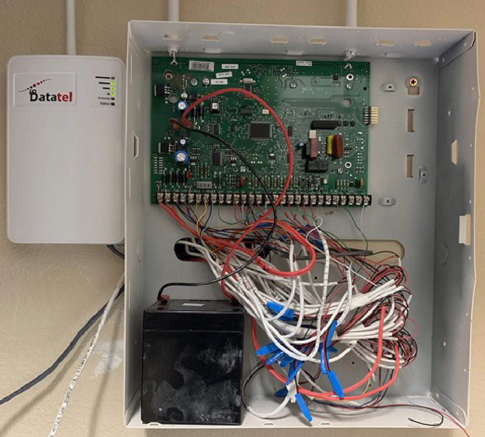
Home security systems usually mean expensive boxes in an obscure place in your house with a bundle of messy sensor wires hooked up to a circuit board, dumb keypads from the 1980’s and other uninspiring tech. You know, like what I had in my house?
Konnected Security
Some monitoring companies have come up with more modern solutions, at a price. This stuff isn’t all that complicated though… shouldn’t there be a better way?
Yup! A successful little Kickstarter last year took an interesting approach at this challenge, with a fun DIY twist: hook up your existing wired sensors to a circuit board and it adds them as things in SmartThings. SmartThings has a feature called Smart Home Monitor (SHM) that lets you use your SmartThings things as sensors triggering an alarm.
If you want 3rd party monitoring, there are even solutions that integrate with SmartThings SMH too.
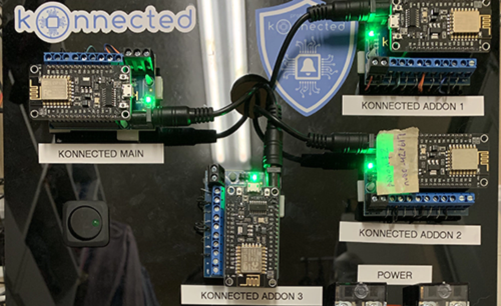
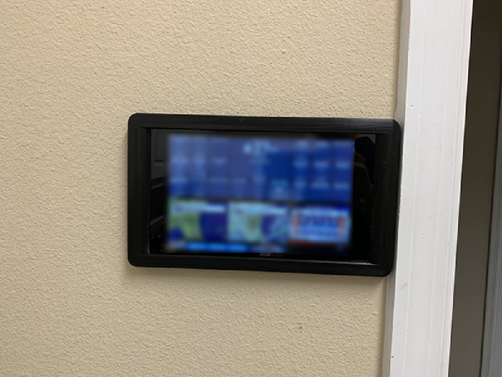
Over the winter break, I had some fun making our house more of a smart home by replacing the security system and installing a few DIY kiosks.
Konnected Security
Konnected Security
You might still ask yourself “yeah… but why did you do this?” I’m interested in microcontrollers and working with hardware, so this was just a little hobby/fun project.
In this post, I’ll walk you through the process.
Parts List & Set up: Konnected.io
First up, let’s go shopping! Some of this stuff you don’t need, some stuff you do. I needed everything and my only screw up was that I bought a few too many terminal strip blocks. I also already had the following tools:
- duct tape - it’s not a DIY home project without duct tape
- painter’s tape
- wire strippers
- wire cutters
- needle nose pliers
- various screwdrivers
- wire fish tape - used to run wires through the wall
- scrap acrylic - used as the mounting board
- assorted wire zip ties & tabs
- 9yr old - these are awesome… they do great holding wires & yelling across the house to you when indicators say sensors are open… definitely pick one of these gems up or borrow one from a neighbor, however, they are hard to handle when testing the indoor siren
So what was on the shopping list?
- konnected.io 24 zone system - 1ct main alarm board, 3ct add on panels
- konnected.io backup battery
- 2ct 12V to 5V converter - used to power the tablets via the existing security system keypad wiring
- 1ct LED 12V rocker switch - picked this up from local auto parts store
- 1ct SPST toggle switch
- 3D printed tablet frame
- 500’ 22 gauge 2 conductor alarm wire
- 100’ 22 gauge 8 conductor wire - used for the keypad, motion detector wires & running some wires on the mounting board
- 200ct b-style splice connectors, crimp style
- 2ct 6-position dual row screw terminal strip blocks
- 9ct 8-position dual row screw terminal strip blocks
- 1N4148 Small Signal Fast Switching Diodes High-Speed Axial 200mA 100V - used to keep static electricity from nearby lightning strikes from damaging the boards
Now that you have all the parts and your Konnected kit, get everything set up. There are multiple steps, but it only takes a few minutes and their instructions are easy to follow. Start here: Unboxing your Konnected Kit.
Note: Make sure you read through the entire install process on the Konnected site, starting with the unboxing link above. They’ve done a great job at documenting everything. You’ll get a good overview of the whole install process. If you have questions, post a question to their forum or the user group on Facebook: https://www.facebook.com/groups/konnected.io.
Prep Existing Wiring
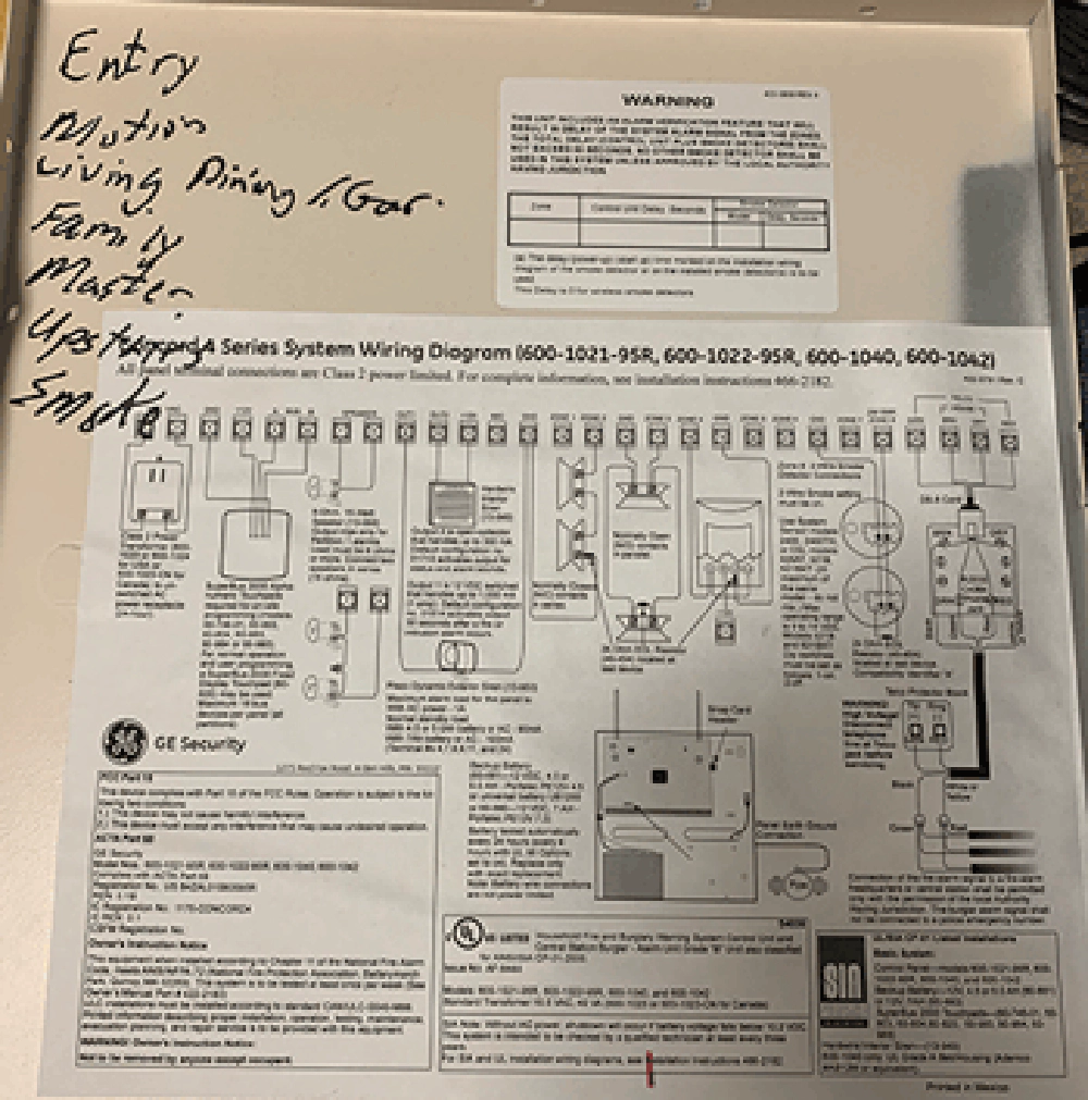
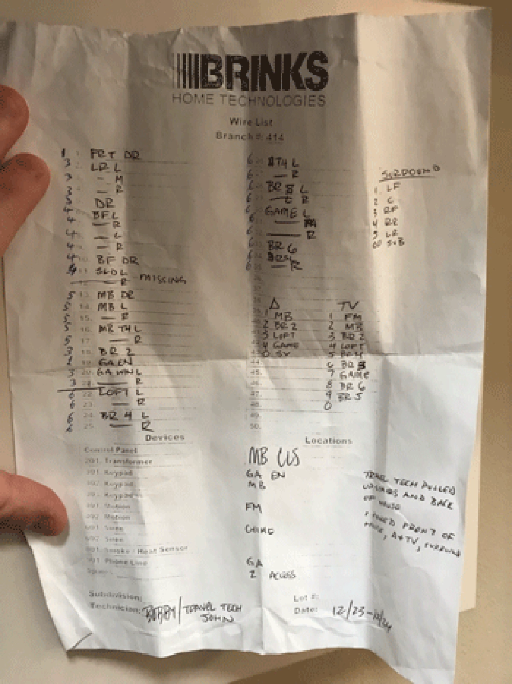
The most tedious part of the whole project was the preparation. When you look at the before & after pictures above, you can see quite a lot changed. I started with a mess of sensor wires. Documentation was less than ideal.
Konnected Security
Konnected Security
It seems that in order to install a security system you have to use as few letters as possible and sloppy handwriting.
Test & Document All Existing Sensors
Test all sensor wires. You can use a multimeter if you have one & know how to operate it. I found it easier to hook up 6 sensors at once to the main board and test opening each one, watching the sensor status change in the SmartThings app on my phone.
If you do this, make sure you document where the wires were connected in your old security system. Before removing any wires, read the next section on Disconnect the Old Security System Panel first.
Go to each door & window, testing every sensor. There was only one sensor not working. That ended up being a result of when we had our house painted recently; somehow the paint was making the sensor think it was always closed. Scraping the paint fixed it.
Make a spreadsheet of all sensors in the house and label / relabel each sensor wire.
This process took a few hours, but it was easily the best time investment at the start of the project.
Some additional comments on the existing wiring:
- Open/closed sensor wires are typically a pair of wires: one red & one black. A security system can tell when a sensor is “broken” (ie: a door/window is open) because the circuit is broken.
- In the pictures below of my wiring, these are the thin white wires that were extended with black wires. I used 22 gauge wire with 2 wires in the insulation (AWG 22/2).
- Some sensors require power, like motion and smoke detectors. These are usually four wires: two for power & two for the sensor signal.
- In the pictures below of my wiring, these were thicker white wires that I extended with bigger white wires. I used 22 gauge wire with 4 wires in the insulation (AWG 22/4).
- I didn’t use the existing smoke detector from the old system. A few years ago I replaced our existing smoke detectors with NEST Protect’s. I then connected them to SmartThings using NST Manager. This is a better set up than my old system. The old system only monitored a single detector. All the other smoke detectors were just “dumb”… they just sounded an alert on smoke but weren’t connected to each other or our monitoring service. This new set up now has every smoke & carbon monoxide sensor integrated with my home monitoring via the SmartThings Smart Home Monitor.
- Keypads are also four wires: two for power & two for data.
- In the pictures below of my wiring, these were thicker white wires that I extended with bigger white wires. I used 22 gauge wire with 4 wires in the insulation (AWG 22/4).
- Sirens can vary… I have a single indoor siren that is triggered by sending it 12V.
- In the pictures below, these are the thick pink wires. I extended these with thicker 18 gauge wire.
Disconnect the Old Security System Panel
With everything documented, you can now slowly start removing everything. Being overly concerned about screwing something up, I recorded a video of me tracing all the wires and how they were hooked up before removing a single one from the old security system.
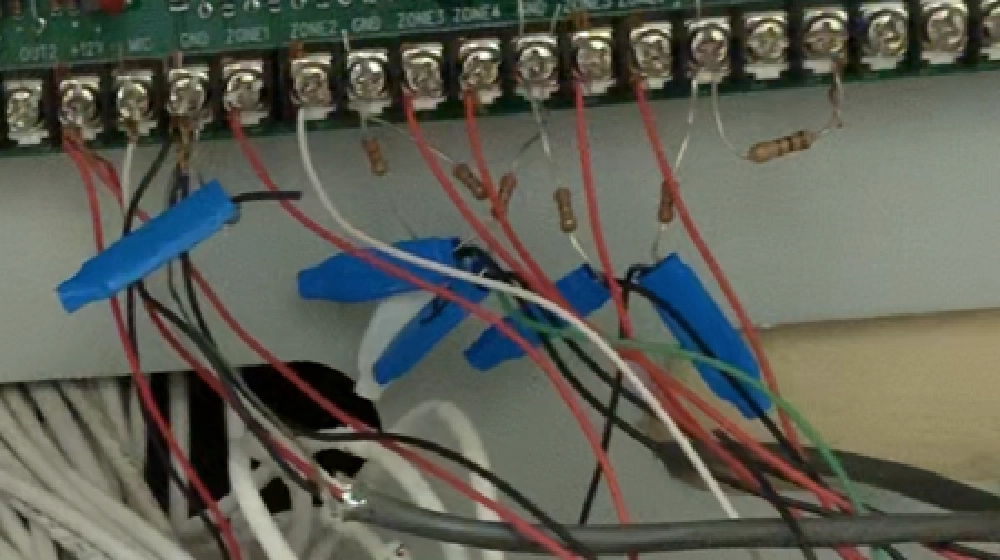
You will likely see a bunch of resistors & b-clips (the blue things in the following picture) from the initial install. You can remove all resistors & b-clips… the resistors aren’t needed with Konnected. As for the b-clips, you’ll likely want to join zones differently than the old system did it.
Konnected Security
My original system had 6-zones, but the Konnected kit I got was for 24 zones. In the end, I broke mine up into 22 zones. How did it change? For instance, we had one zone called “Master”. That got split into 4 zones: one for a door to the outside patio, one for each of the two bathroom windows & one that joined the two windows in the bedroom.
Bonus: Clean Up the Wiring Install
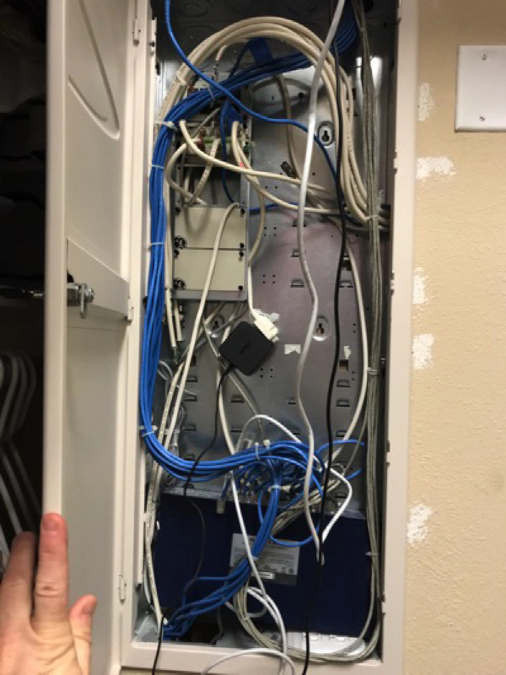
A clean workspace is a pet peeve of mine. I wanted to remove the security panel in my closet and move the entire set up to the structured wire box that was already there. A month after we moved in, this box was an absolute mess:
Konnected Security
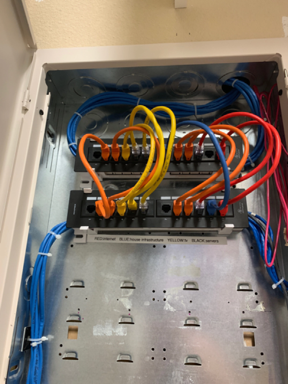
Last year when I renovated our home office network, I cleaned it up quite a bit:
Konnected Security
But all that extra space at the bottom could be used by the security system. This meant I had to create extensions for each sensor wire and fish them through the wall. This added a solid day to the project… but I like how it turned out:
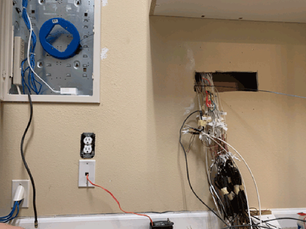
Konnected Security
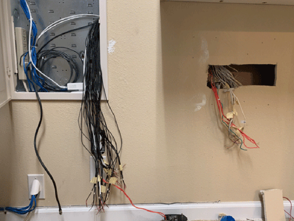
Konnected Security
Planning out the Zones
The last step before installation and hooking Konnected up was to plan the zones. As I said previously, I was breaking out from a 6-zone system to a 22-zone system for better visibility. This didn’t mean that every single sensor was on its own zone. But things could be grouped together in a better way.
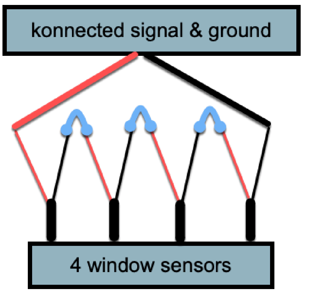
For instance, we have 4 windows in our kitchen. We joined these as a single zone “kitchen windows”. You then wire these together in a series so when any one sensor’s circuit is broken, the whole circuit is broken:
Konnected Security
In this picture, you can see the four wires going down to the four different sensors that make up my kitchen windows. Then, one wire from each of the two outer sensors will be connected to the Konnected board, while the others are joined together in a series. If any one window is opened, the whole logical unit is seen as being open.
Konnected System Installation
Check out the install docs on the Konnected site, they do a great job walking you through the process. I wanted to make my set up nice and clean… something I’d be proud to share. You can get some great ideas from looking through pictures in the Konnected User Group on Facebook.
I did lots of mapping things out trying different layouts. In the end, I had just a few requirements:
- The final build needed to be stable - with so many wires, I didn’t want to have a chance of bumping something out of its connection.
- Portable - not in the sense that I wanted to tote it around, but I wanted to easily pull it out of the closet’s structured wire box onto the floor where I could work on it.
- Hide the wires away.
- Killswitch for the siren while I tested things.
- Killswitch for power
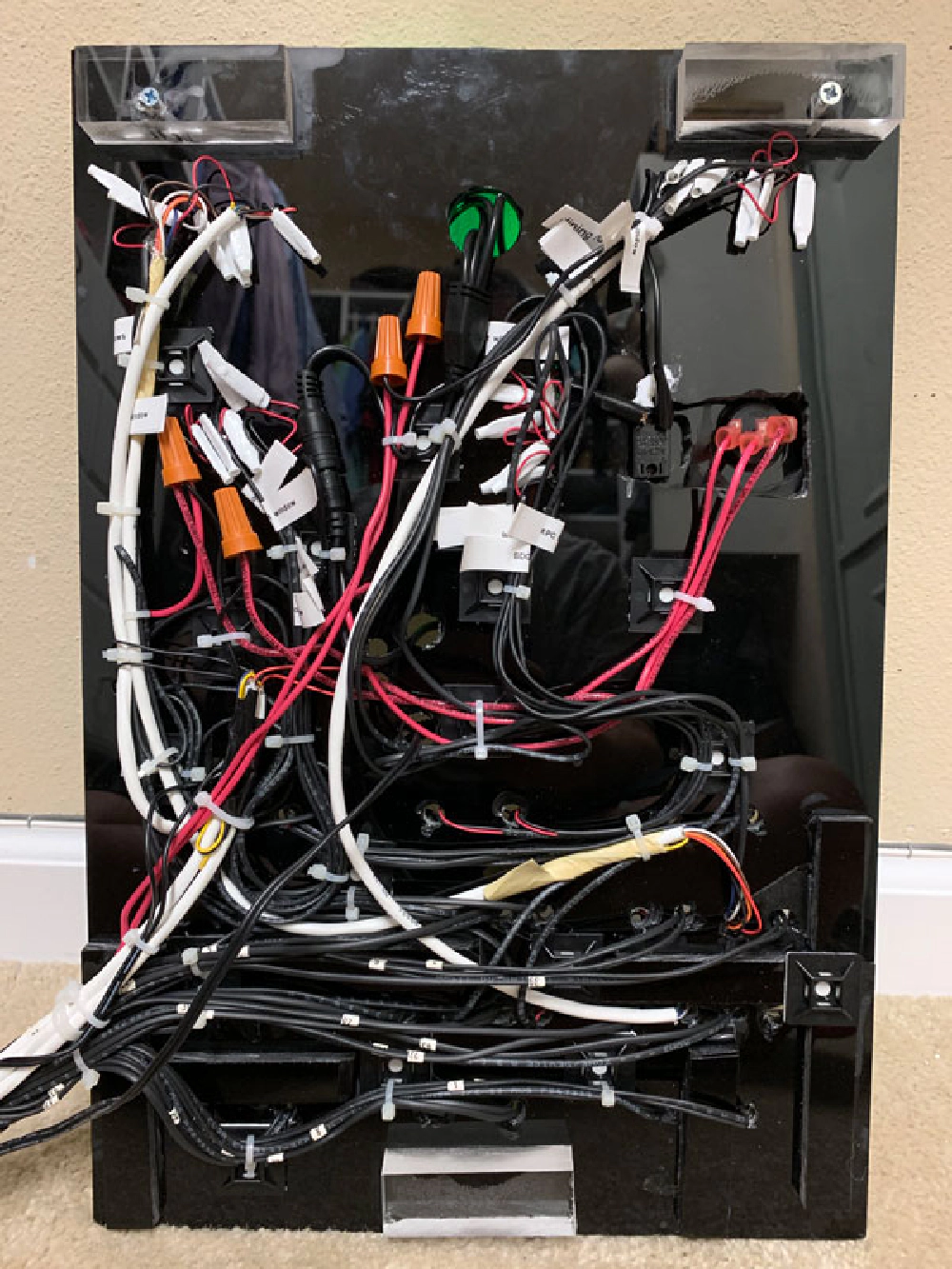
The board is a scrap piece of 1/4" acrylic from a previous project. I like working with acrylic because you can glue it together easily, but it’s brittle if you don’t use the right tools. If you look closely at the back, you can see where it cracked and I had to glue scrap black strips to hold it together.
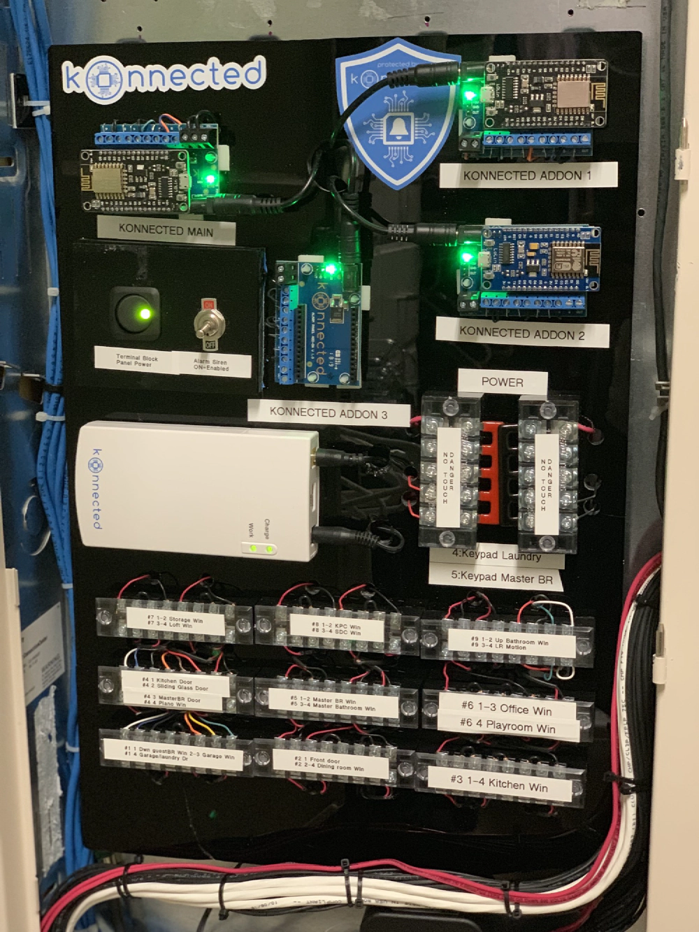
I settled on the following layout:
Konnected Security
Konnected Security
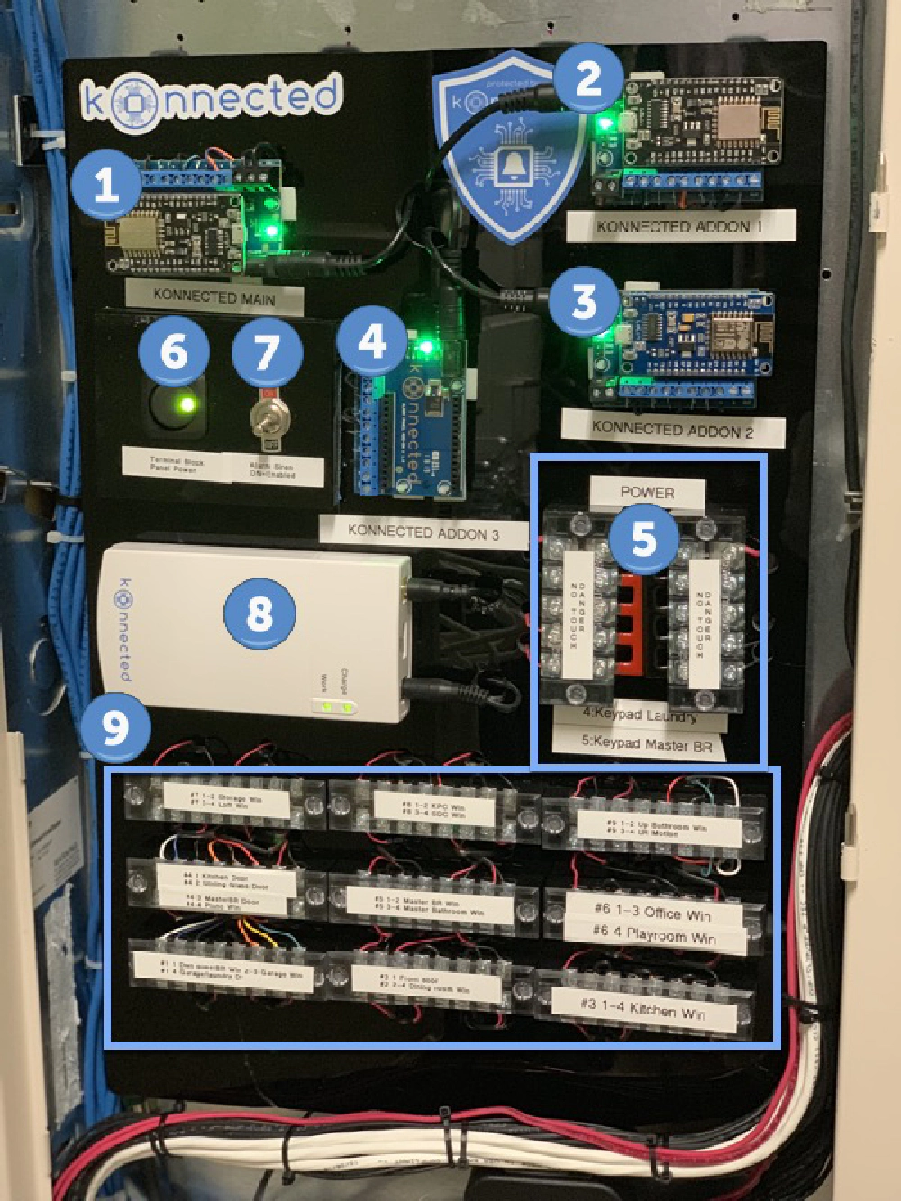
Let me explain how it’s organized:
Konnected Security
Konnected Boards (#1 - 4)
These are the brains of the set up. The sensor wires are all hidden up through the underside of the board. Each one comes through its own pinhole.
Each sensor wire is connected to the board via a diode to protect the boards from nearby lightning strikes… common in Florida where I live.
These sensor wires go down to the 9 terminal strips (#9) at the bottom of the board.
Sensor Terminal Strips (#9)
All wires from the security system sensors, keypads and siren (black, white & pink wires) come into the structured wire box from the right. There’s about 2’ of slack tucked into the cavity in the wall.
Each sensor is connected to its own position on the terminal block, coming up from the bottom. The wires that go to the konnected boards are connected to the terminal strips from the top.
This made is very easy to mount all the konnected boards and test everything was set up the way I wanted it before attaching the sensors and being stuck in the closet where the structured wire box is. Instead, I could wire the whole thing up at our kitchen table.
This also made it very easy to create the zones. Recall the diagram above when I explained how I created wired sensors together to make a zone? Let me zoom in on my kid’s bedrooms who each have two windows:
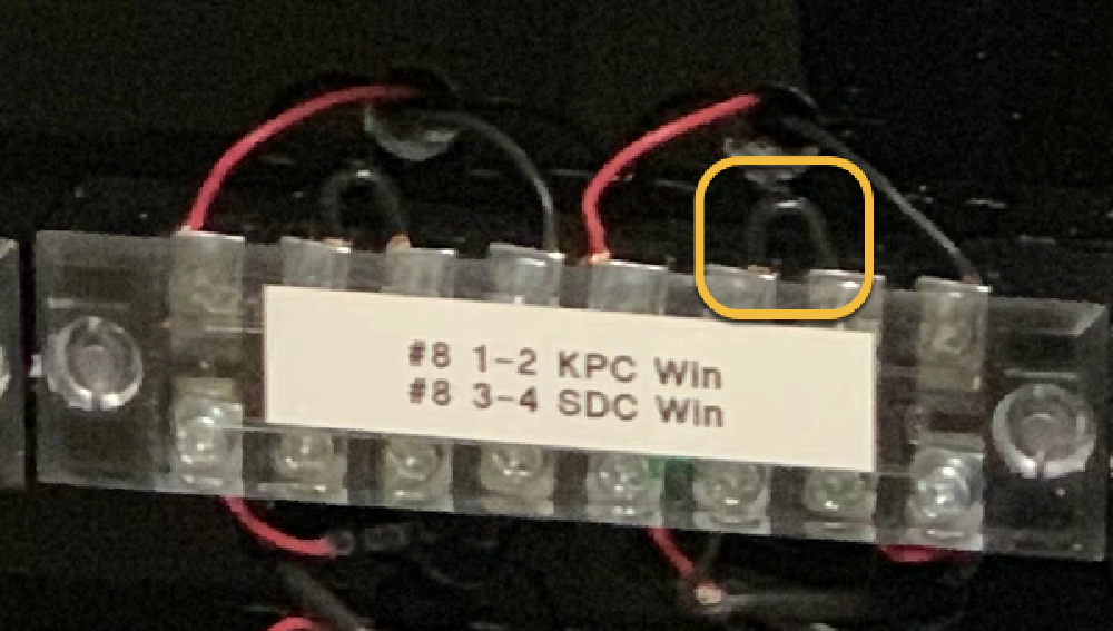
Konnected Security
It’s hard to see on the black acrylic, but look at the black jumper wire I circled in yellow. That’s connecting the two windows in my son’s room (SDC) in a series. My daughter’s room (KPC) is set up the same way as you can see just to the left. See if you can find the kitchen windows… that took up its own terminal strip as one zone!
Powering the Security System (#8)
What you can barely see is one of two little 12V transformers plugged in just to the bottom right of the board in an outlet in the structured box. One of these is connected to the battery as input. The output is connected into a 4-way splitter that is connected to each Konnected board.
That’s basically it! There are just two more things to cover: the siren & powering the keypads kiosks.
Wiring the Siren (#1 & #7)
The existing siren is triggered by sending 12V to it. The main alarm panel for Konnected has two ports for this… you can read up on it in their docs here. It’s a little hard to see in the picture, but two black wires are going into those black screw terminals on the main board (#1).
The siren wires are the two pink wires that come in with the main bundle to the right. In the middle of the back of the board, those two pink wires are changed up to black and the negative wire goes through the toggle switch. This acts as a kill switch #7, letting me trigger the alarm without driving my family and dogs crazy. It also lets my wife or kids kill the alarm if things go haywire when I’m gone. Hey… it is a DIY project… no one is hiring me to do this.
Kiosk Panels
At things point, everything can be controlled through our phones using the SmartThings app, but I wanted to take it to the next level and add a cool factor to it. I installed a few cheap Kindle Fire HD 8" tablets ($50/each new). My post explains how I set them up: Using a Kindle Fire as a Home Kiosk for SmartThings & Smart Home Monitor. In this post I want to talk how they were wired up.
The old security system keypads had wires going from the system to the keypads. I used those as the power supply to the tablets. On the tablet side, the wires are hooked up to a 12V to 5V converter with a right-angle microUSB connector.
One is mounted using a 3D printed wall mount with a channel for the USB charging cable. It covers the existing hole in the wall where the keypad was.

Konnected Security
There wasn’t room for a 3D printed frame for the other one as they slide in from the right. So I took two 3M strips, attached them to small strips of acrylic that I screwed to the existing gang box in the hole behind the other panel and attached the other table to it.
Now… how to power these guys?
Powering the Kiosk Tablets (#5 & #6)
If you go back and look at the board, you’ll see two more 6-position terminal strips vertically mounted. One is positive power, one is negative. The two bottom positions on each strip are connected to the wires going to the keypads that come into the structured wire box with the rest of the sensors.
What you don’t see is another 12V transformer plugged into a SmartThings plug at the bottom of the picture. The wires for that are connected to the LED rocker switch (#6) and then over to the top of the two terminal strips. This lets me kill power to the keypads if necessary without fiddling with a plug.
The SmartThings plug is set up on a workflow to cycle being turned on for a few hours and then off for a few hours. This will keep the batteries in the tablets from possibly expanding and potentially being a fire hazard.
Install Complete!
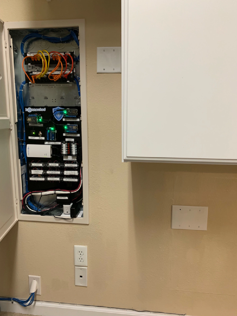
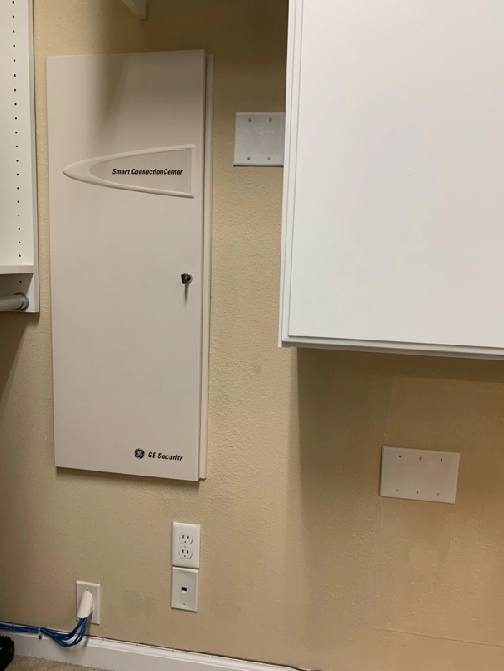
All that’s left was to put the board into the structured wire box, tuck the excess wire into the wall, patch the hole in the drywall where the old security system was, and paint. Nice and clean!
Konnected Security
Konnected Security
I didn’t get a before picture, but the old security box used to be where the three-gang panel is under the cabinet to the lower right. I didn’t want to completely seal it up in case I needed to get to one of the security wire extensions I had to create.
Configuring Konnected, SmartThings Smart Home Monitor & webCoRE
The last thing to cover is the configuration. To be honest, I’m still working through this. I’m pretty happy how it’s set up right now though. My post on Using a Kindle Fire as a Home Kiosk for SmartThings & Smart Home Monitor explains how I use ActionTiles, so I won’t duplicate that here.
But I love how using SmartThings and our phones as presence sensors, the alarm turns itself on automatically 10 minutes after when we all leave the house and automatically turns it off when just one of us returns.
I’m still working on a delay trigger so the alarm doesn’t trigger immediately when we walk in if the presence sensors are a little delayed. It’s just a configuration thing… most people are using the SHM Delay Switch, which I am trying to configure, but so far I’m having issues. Nice to have that siren kill switch right now! We have the siren disabled while I get this sorted.
Until then, we’re just using our phones & the kiosks to disable it on the rare instances the presence sensors don’t work.
I’m also using webCoRE as a workflow app that is handling the cycle on & off of the tablet power plug among a few other things.
All in all, this has been a fun project and I love how it’s turned out! If you’re looking to do something like this, I hope this post has helped give you a few ideas.
Got a question? Post it below!